SoundMachine Build Log 02

I've decided to put in a knob to control the volume directly on the box itself. It will be controlled by volumio itself via a plugin, much like the GPIO Buttons plugin.
Since this is really a development kit approach, the hardware consists of:
- A KY-040 rotary encoder and
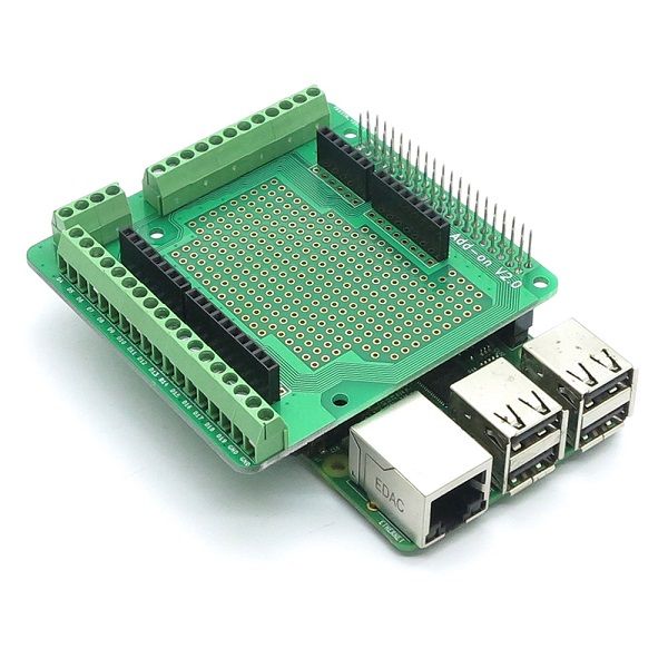
- A screw-based prototype board
Both are relatively easy and cheap to find and buy.
Rotary encoder
The encoder is straight-forward cheap version, with a push button too, just in case. It's even mounted on a PCB and has pins too, so it's practically plug-and-play
The prototype board
The board looks like this:

This allows me to connect the clock pin (volume UP), data pin (volume DOWN) to e.g. D7 (GPIO23) and D8 (GPIO24) respectively. Now, we only need to create a plugin to put the encoding in the right place. Next post will detail the software side of volume control :)
Annex - Mapping
The mapping between raspberry pi pins, GPIO and the screw-able parts is:
| Raspberry PI Pin N.O. | Pin name | Arduino Shield | Description |
|---|---|---|---|
| 1 | 3.3V | 3.3V | |
| 2 | 5V | 5V | |
| 3 | GPIO02 | A4 | SDA |
| 4 | 5V | 5V | |
| 5 | GPIO03 | A5 | SCL |
| 6 | GND | GND | |
| 7 | GPIO04 | A0 | |
| 8 | GPIO14 | D1 | TXD |
| 9 | GND | GND | |
| 10 | GPIO15 | D0 | RXD |
| 11 | GPIO17 | D2 | |
| 12 | GPIO18 | D3 | |
| 13 | GPIO27 | D5 | |
| 14 | GND | GND | |
| 15 | GPIO22 | D6 | |
| 16 | GPIO23 | D7 | |
| 17 | 3.3V | 3.3V | |
| 18 | GPIO24 | D8 | |
| 19 | GPIO10 | D11 | SPI_MOSI |
| 20 | GND | GND | |
| 21 | GPIO09 | D12 | SPI_MISO |
| 22 | GPIO25 | D9 | |
| 23 | GPIO11 | D13 | SPI_SCK |
| 24 | GPIO08 | D10 | SPI_CE0 |
| 25 | GND | GND | |
| 26 | GPIO07 | D4 | SPI_CE1 |
| 27 | ID_SD | ||
| 28 | ID_SC | ||
| 29 | GPIO05 | A1 | |
| 30 | GND | GND | |
| 31 | GPIO06 | A2 | |
| 32 | GPIO12 | A3 | |
| 33 | GPIO13 | D14 | |
| 34 | GND | GND | |
| 35 | GPIO19 | D16 | |
| 36 | GPIO16 | D15 | |
| 37 | GPIO26 | D19 | |
| 38 | GPIO20 | D17 | |
| 39 | GND | GND | |
| 40 | GPIO21 | D18 |

